Using the Carlson Calibrator
Calibrating Accelerometer
Calibrating an accelerometer for use with the Madgwick filter is essential to ensure accurate sensor fusion and orientation estimation. The accelerometer measures linear acceleration along its axes, and any inaccuracies, such as bias, scale errors, or axis misalignment, can degrade the performance of the filter. Calibration involves determining and correcting these errors, ensuring the sensor outputs are consistent and reliable. This process is critical because the Madgwick filter relies on precise accelerometer and gyroscope data to compute orientation. Without proper calibration, the filter's output may drift or become unreliable, impacting the performance of the C-ALS and Boretrak.
Setup
The first step is to connect to the tilt-jig. This only needs to be done once on the computer as the connection will be remembered.
First plug in the tilt-jig USB to serial connection to your computer. It might download drivers but will create a virtual COM port. Go to Settings>Boretrak>Motor Link. Note you will need to enter in the Boretrak Maintenance password if you haven't already.
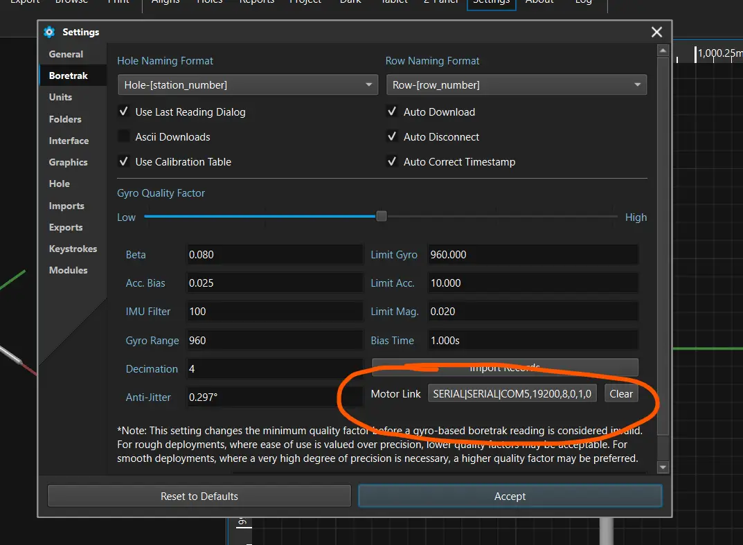
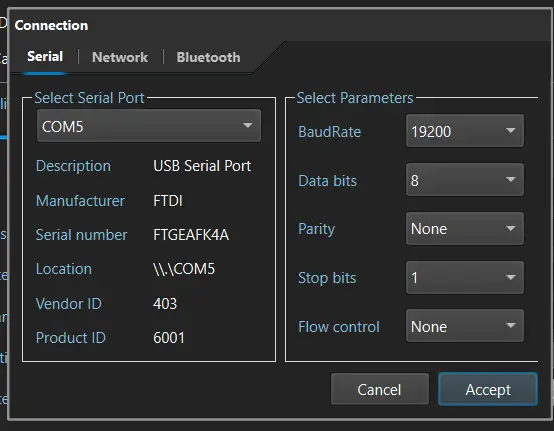
Select the icon and set the connection to serial with a baud rate to 19200 as below, being sure to select the correct COM port (Note the COM port is not necessarily 5 as shown below).
Running the Test
Place the probe in the tilt jig being sure to lock it in place. The rotation does not matter as the software will automatically determine which orientation to run first.
Connect to the probe via the software. Once connected, select the "about" button on the probe, then navigate to Accel Calibration tab at the top.
Be sure that the probe is locked into the calibration jig.
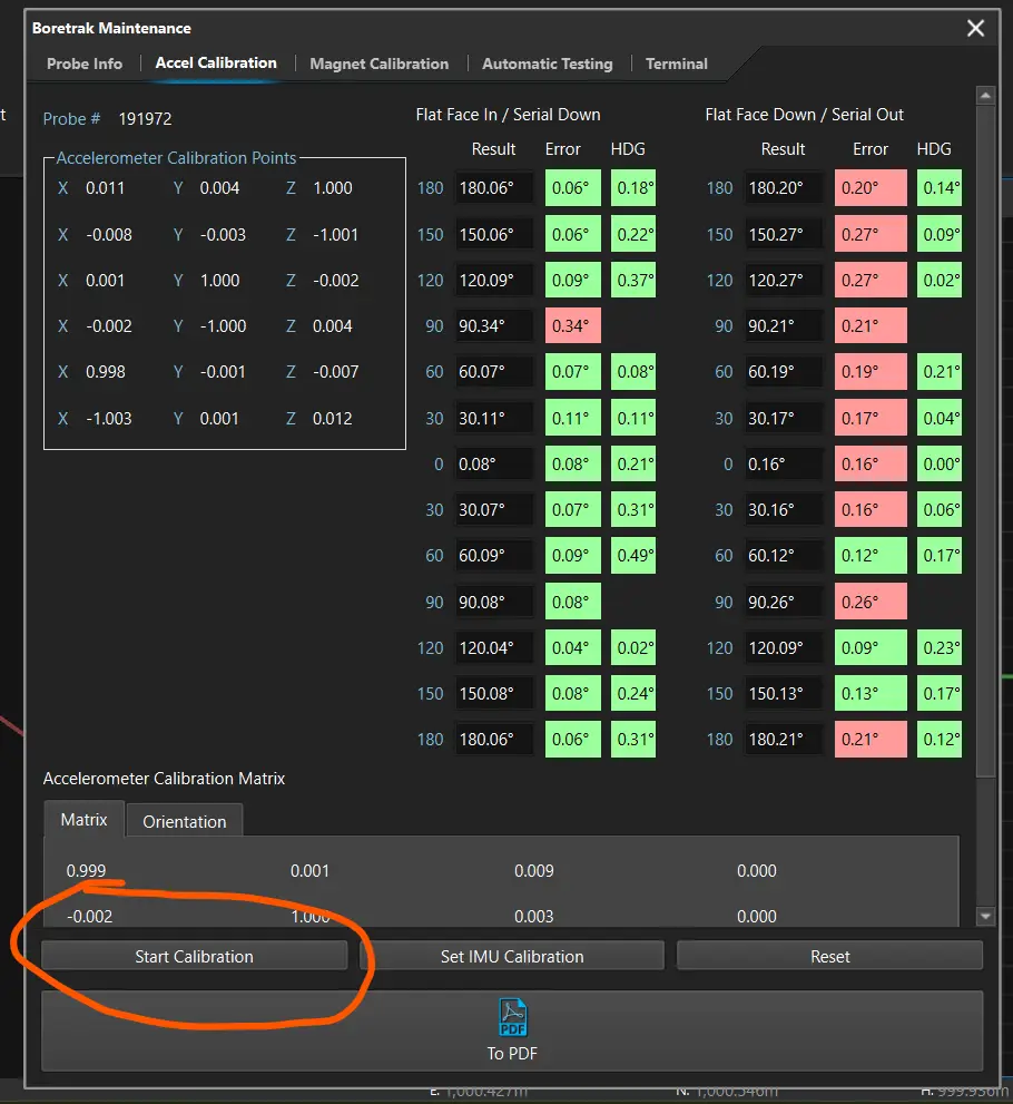
When ready, select "Start Calibration".
Do not remove the probe until the calibration is complete.
Once complete, rotate the probe 90 degrees and click "Start Calibration"
All 4 columns should now be filled out.
Troubleshooting
If a test fails to validate, it may be due to one of several reasons.
Bent Metalwork
- The probe attachment point may be misaligned from the tilt jig
- Test by placing a bubble level on the probe when starting test to ensure probe is level.
IMU misalignment
- The IMU can be misaligned in the metalwork
- Confirm placement of IMU in metalwork
Tilt Jig Not Level
- The tilt jig may not be completely level.
- This can be checked via bubble level
Bad Sensor
- The IMU could be physically damaged
- Run diagnostics on IMU itself.
Understanding Results
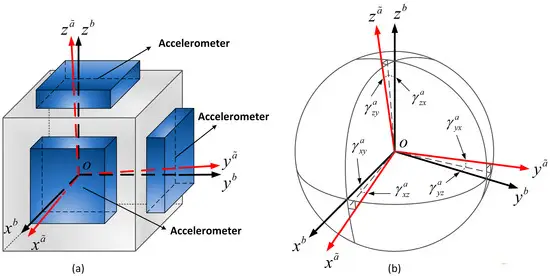
The calibration works by moving the probe 360 degrees about 2 axes. The first rotation is used for creating an offset matrix at each point, the reverse rotation is used for validating the IMU and output.
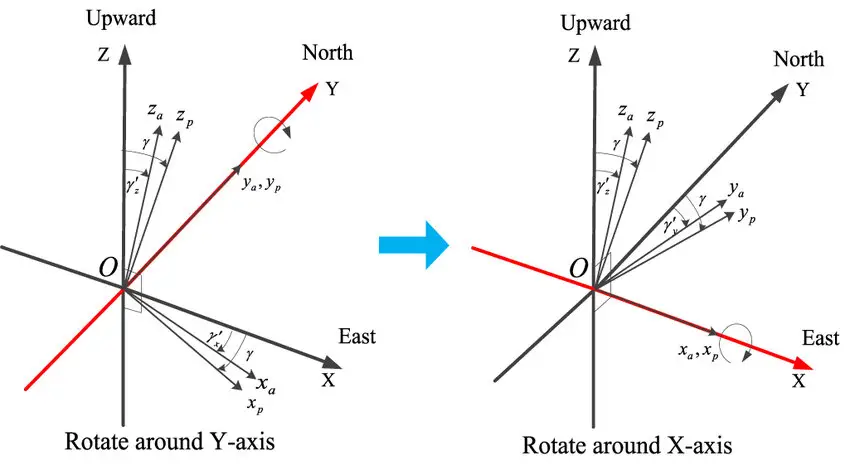
For the calibration, data is collected at 6 key locations:
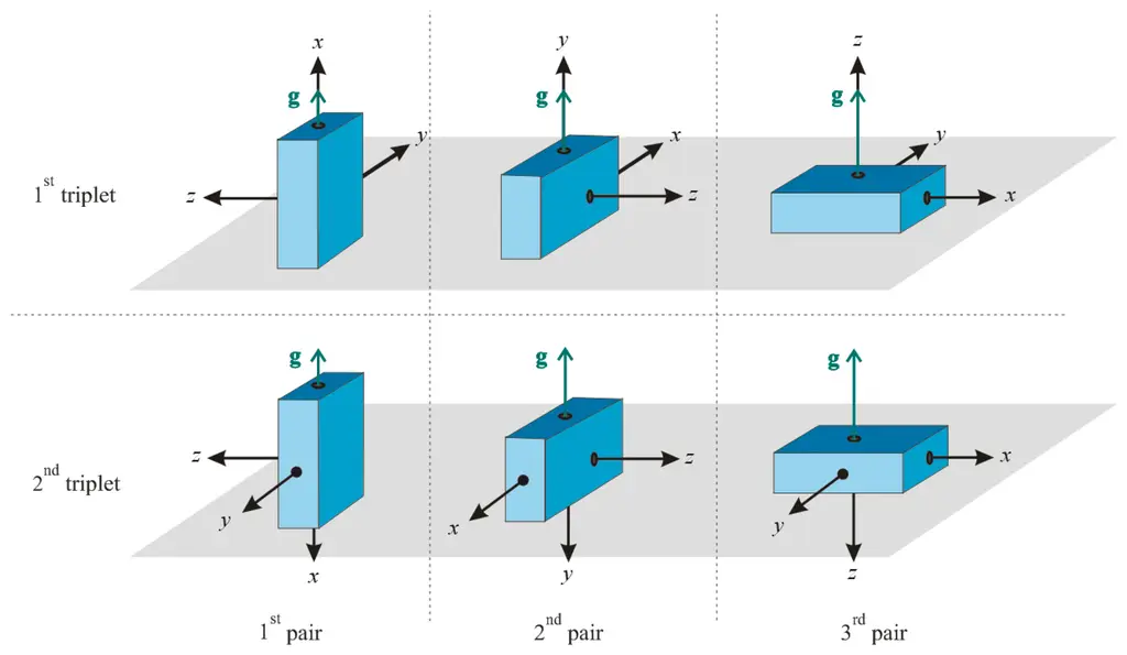
Based on the difference between the measured gravity vector and actual gravity vector at these 6 locations, a least-squares analysis is performed. This allows us to calculate a reference scale and offset for the accelerometer axis.
This offset is then applied to the acceleration reading prior to being used by Madgwick to calculate an optimal orientation.
The calibration is validated via two columns: The first column represents the difference in pitch between the raw accelerometer reading and the value calculated in the jig. This proves the raw acceleration data is in-line with what is expected.
The second column represents the Gyro offset reading. It ensures alignment of the gyro axis with the accelerometer axis. Both columns are critical to measuring angles and tolerence.